Finlay's Case Presentation
Welcome to my December 2020 Newsletter Case Presentation
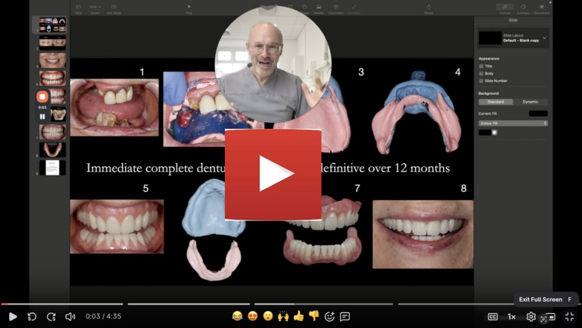
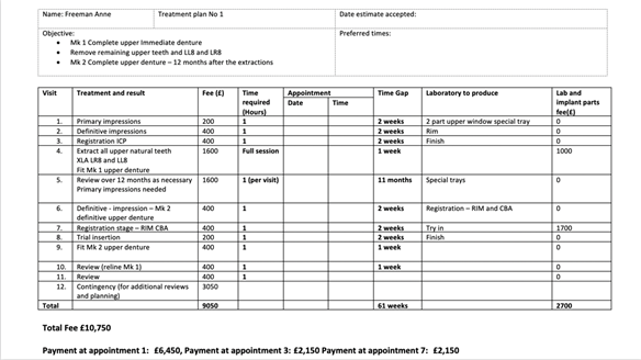
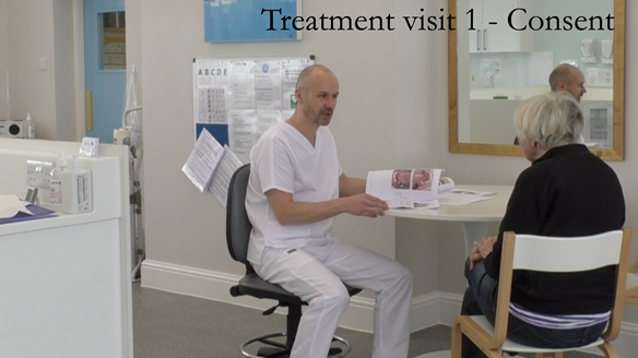
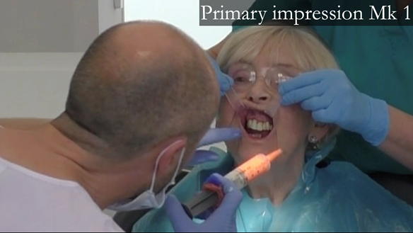
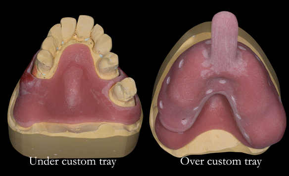
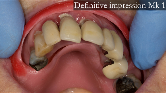
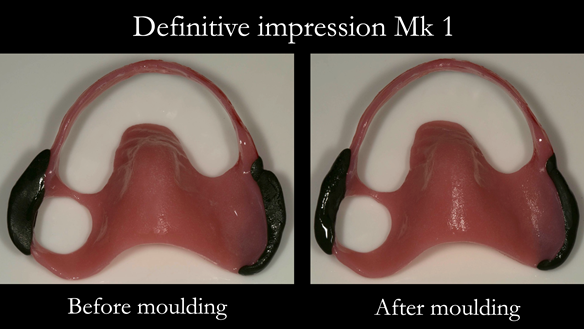
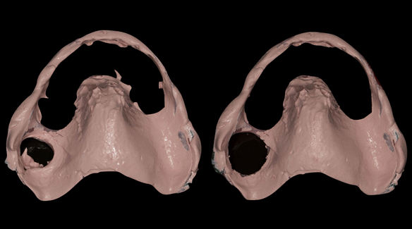
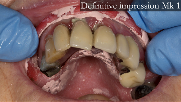
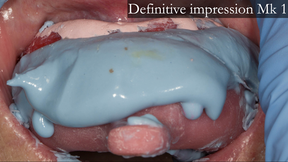
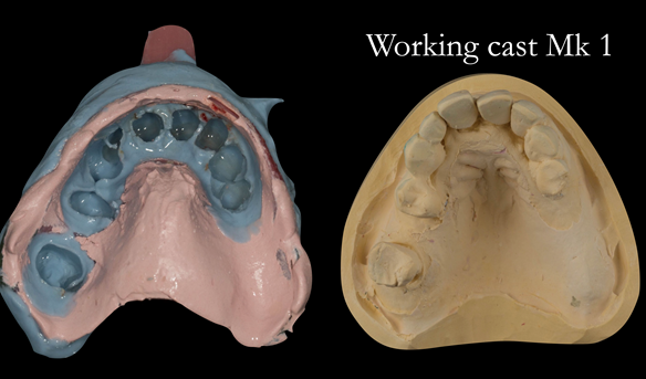
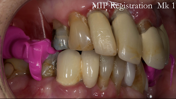
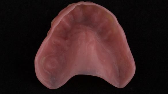
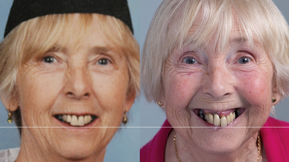
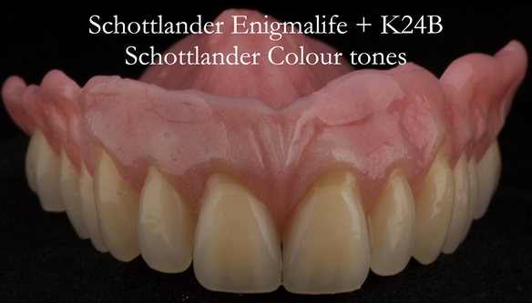
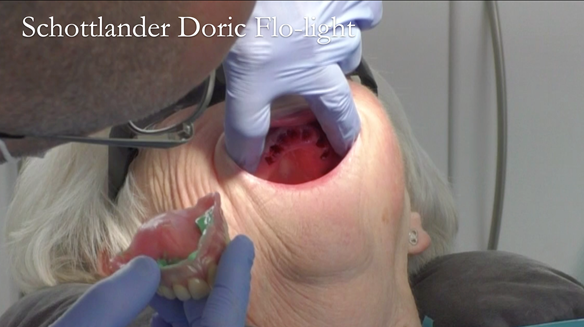
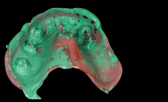
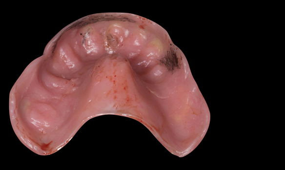
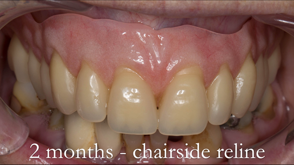
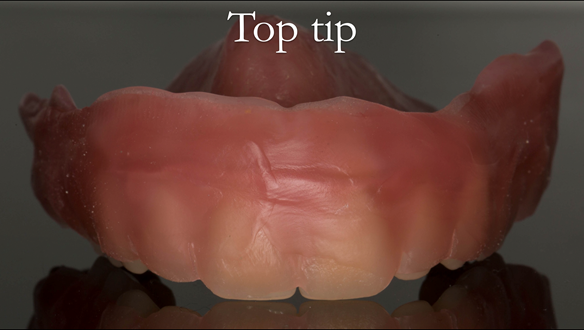
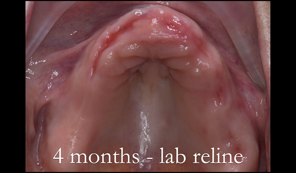
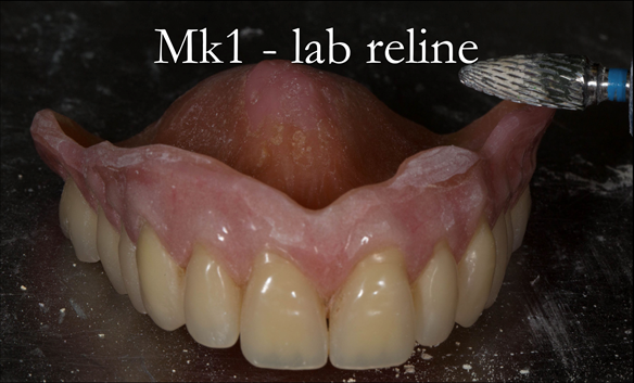
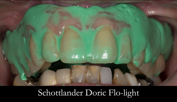
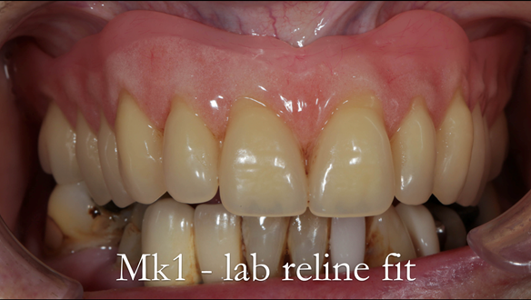
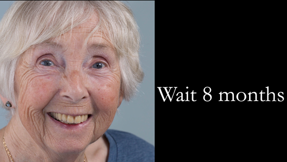
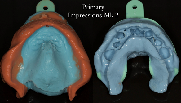
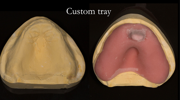
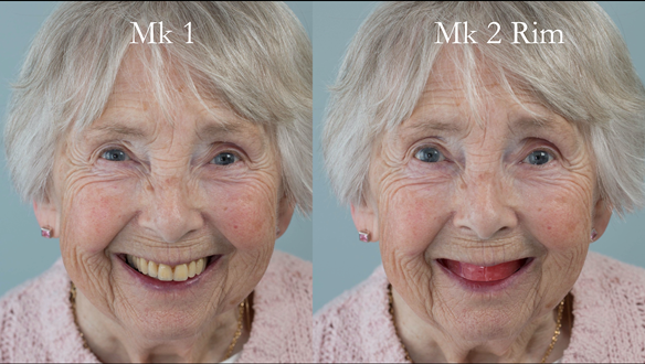
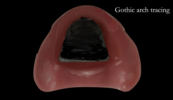
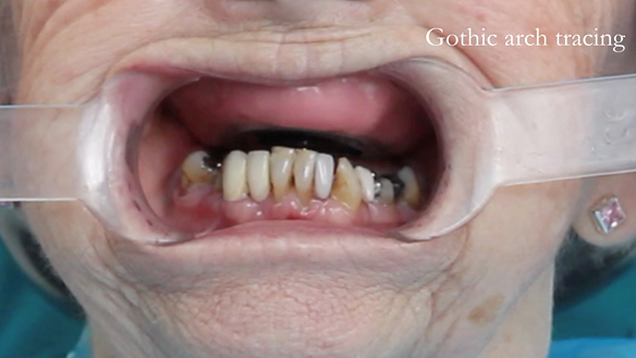
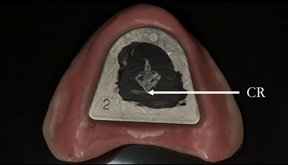
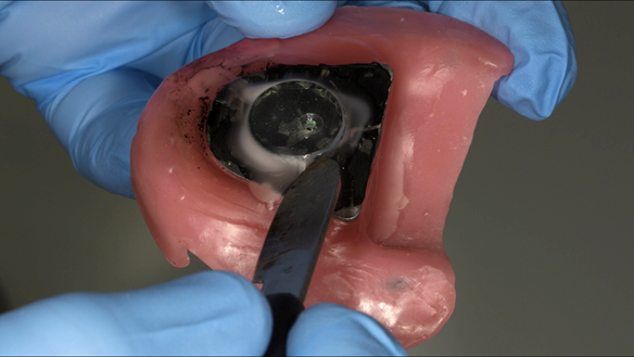
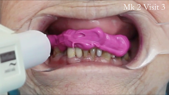
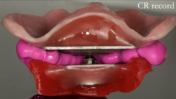
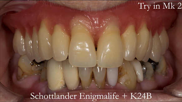
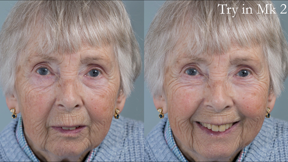
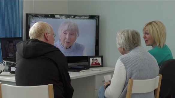
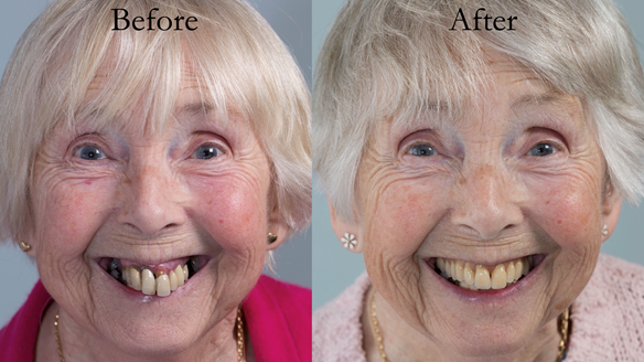
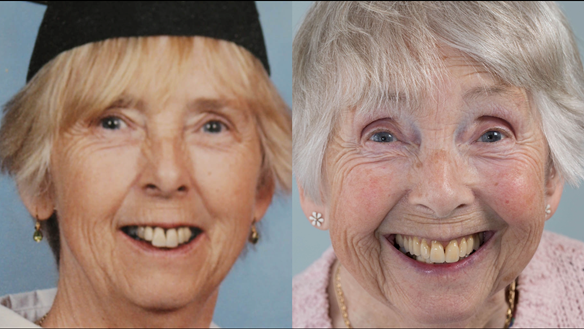
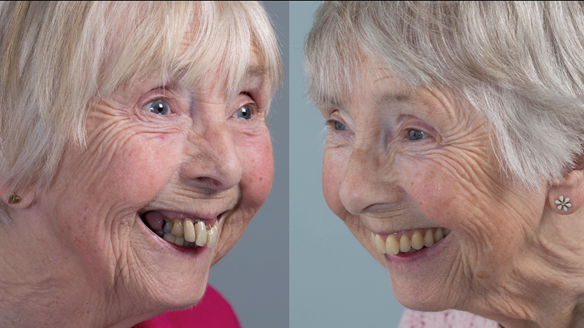
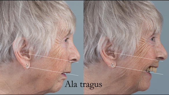
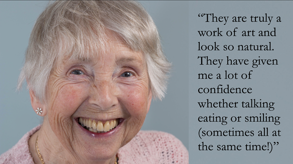
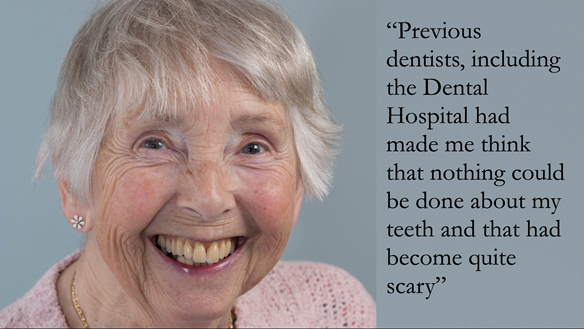
This newsletter describes in step by step detail Anne's transition from an immediate complete upper denture to a definitive complete upper denture.
This 73 year old woman was referred to me by her general dental practiioner for treatment.
Dental concerns
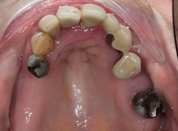
- “Upper teeth/crowns/bridges all loose”
- “Dentures seem the only option”
- “Bottom teeth are not good but still functional”
Medical History
- Anxiety - medication Citalopram and Propanolol
Social history
Retired civil servant
Dental wish list
- “Advise on upper denture”
- “Provide a working denture”
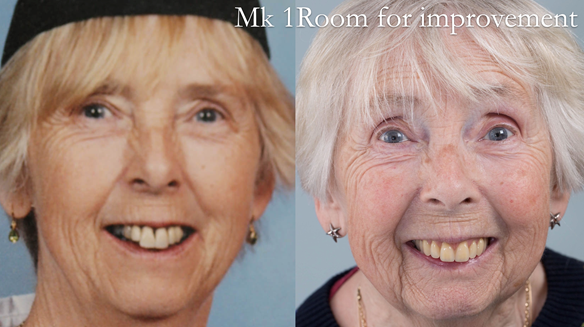
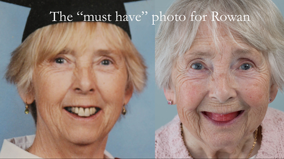
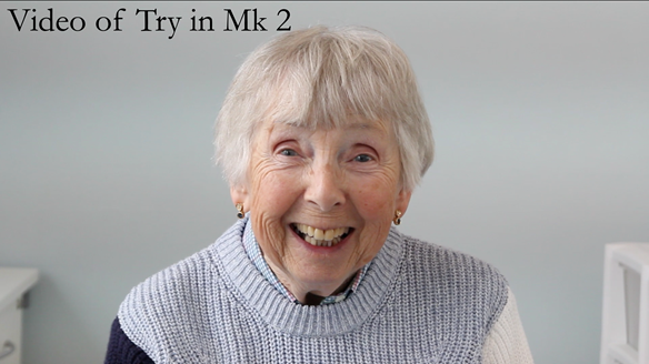
- “Provide a good looking denture”
Diagnoses
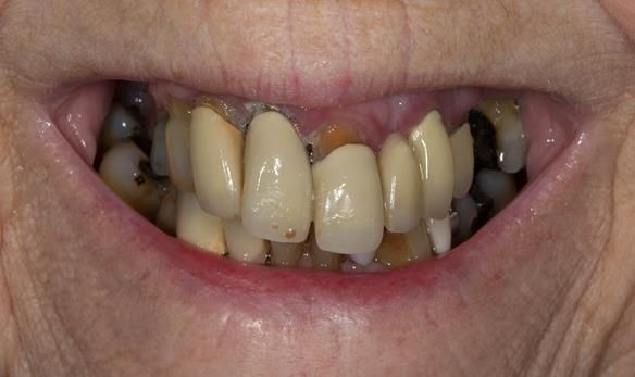
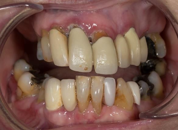
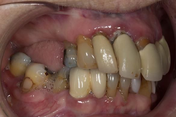
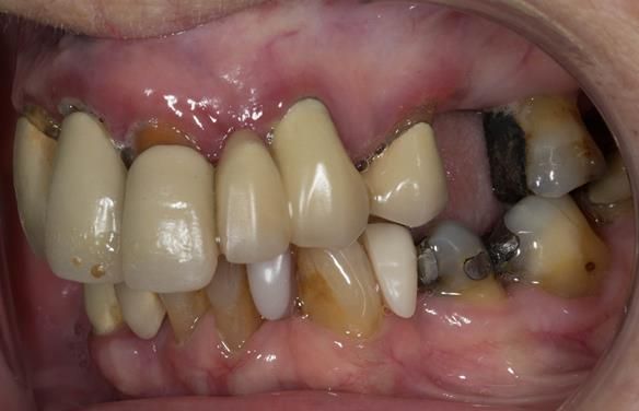
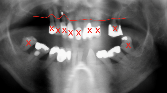
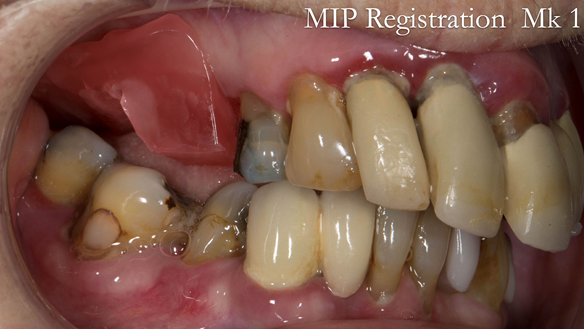
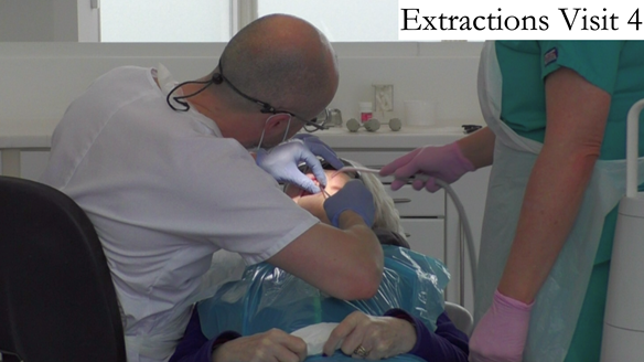
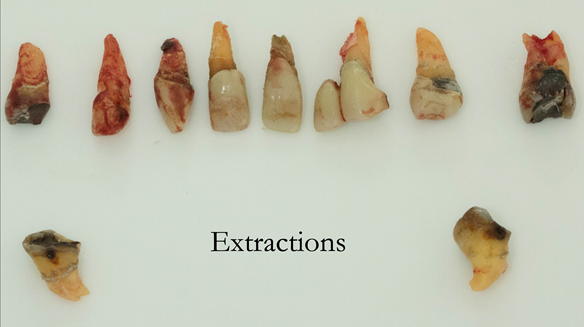
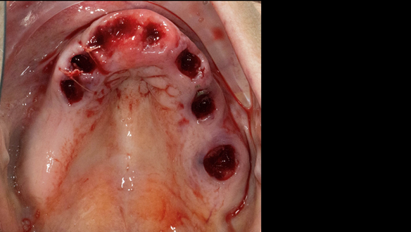
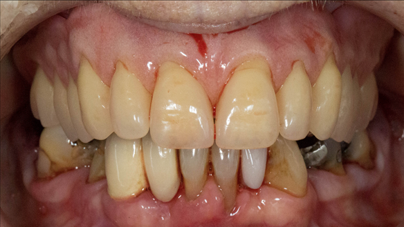
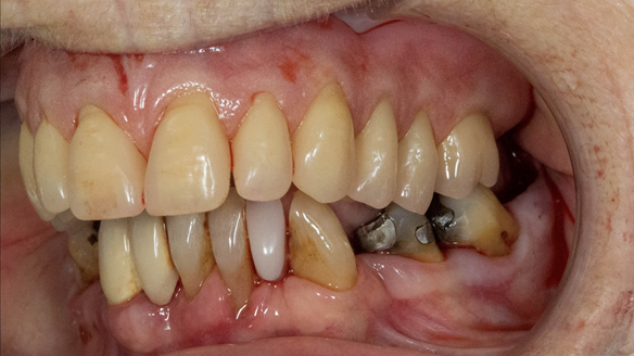
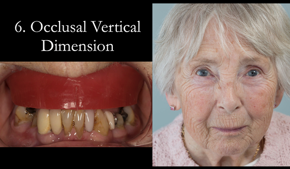
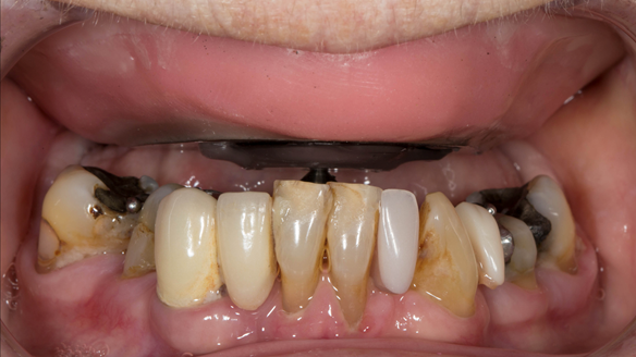
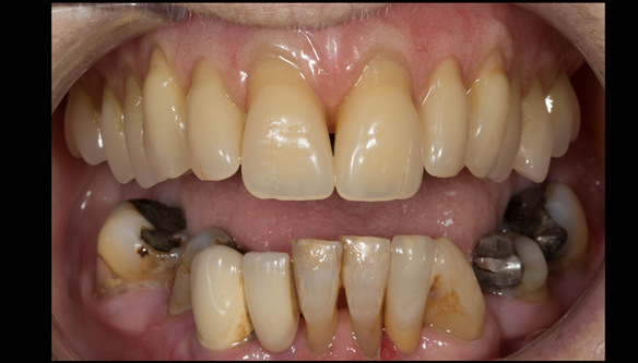
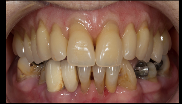
- The remaining natural upper natural teeth and lower back molars were heavily restored having generalised periodontitis stage 4 Grade C. Some of the teeth exhibited caries. The prognosis for these teeth ranged from dubious to hopeless.
- The lower teeth (apart from the lower back molars) had better progniosis and were to be managed by the referring general dental practitioner.
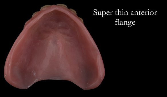
- The upper and lower acrylic based partial dentures exhibited suboptimal extension of the flanges and saddles. They had poor retention, support, stability and tissue fit.
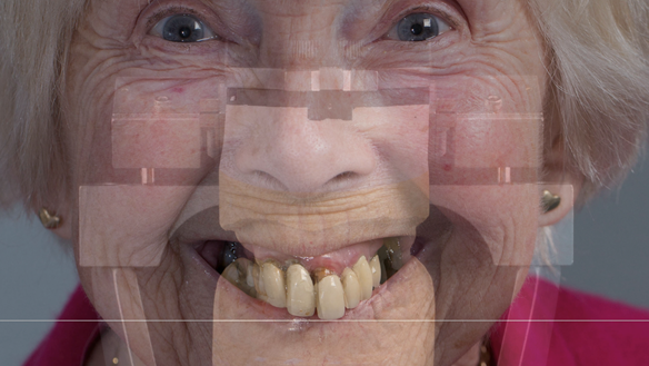
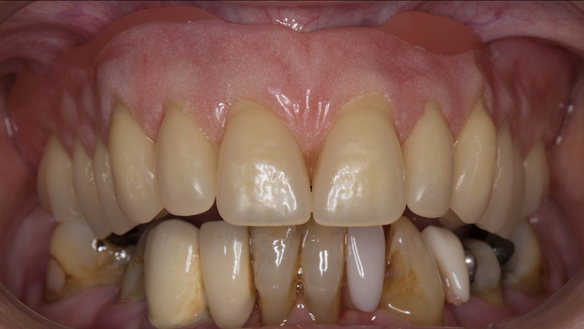
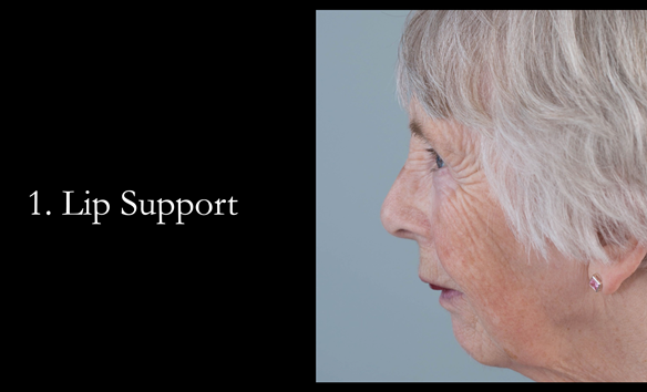
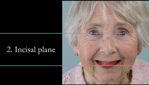
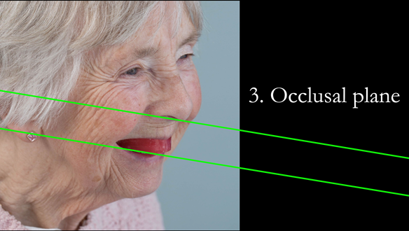
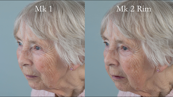
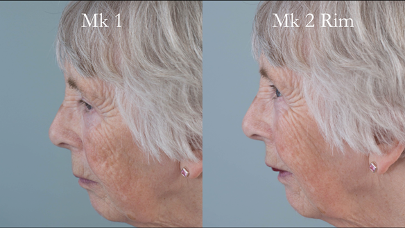
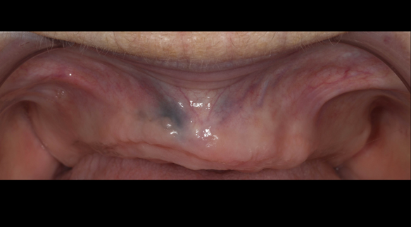
- The patient had a high smile line showing 5mm or more alveolar soft tissue above the upper front teeth during social interaction.
Treatment options discussed for the upper arch
- Do nothing
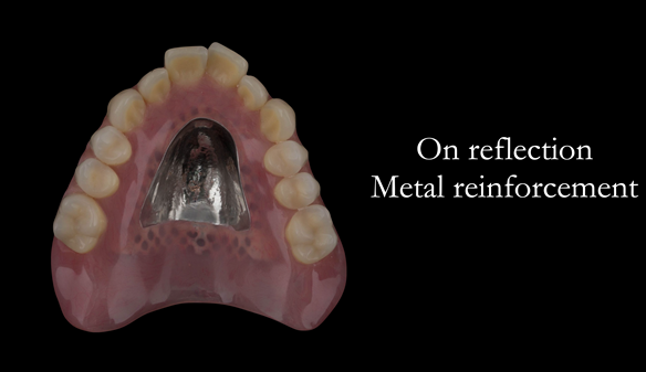
- Complete denture
- Retain some of the teeth and provide a removable partial denture
- Implant supported complete denture
- Implant supported fixed teeth
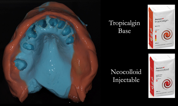
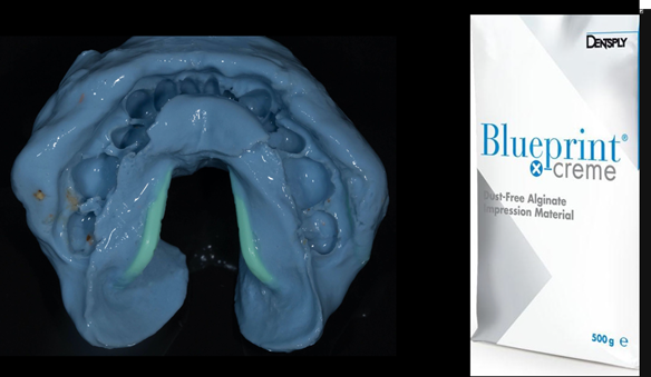
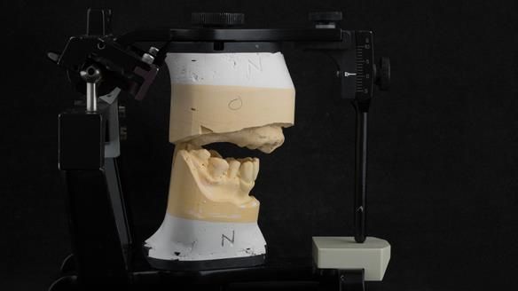
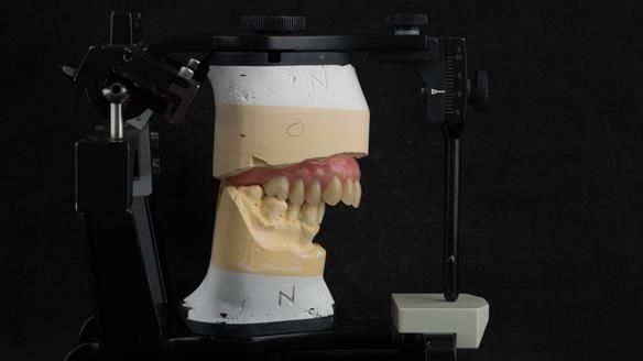
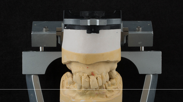
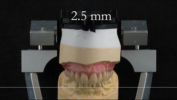
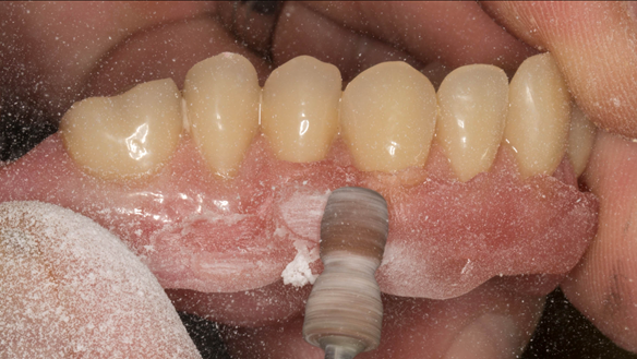
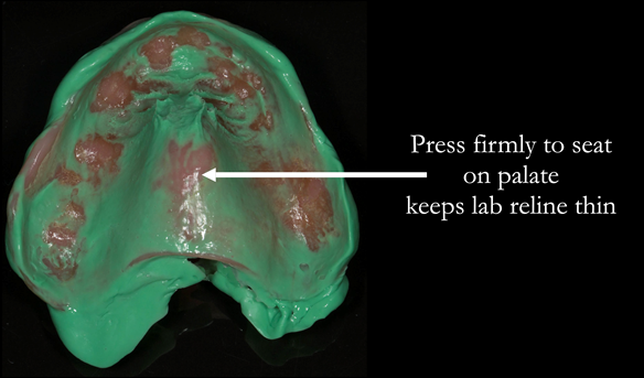
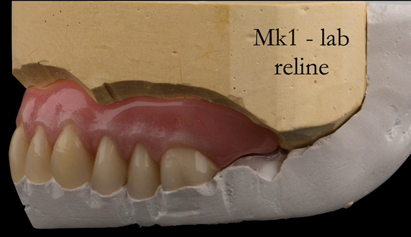
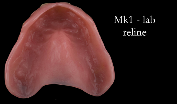
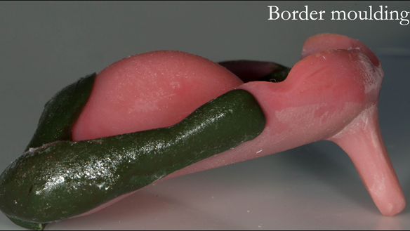
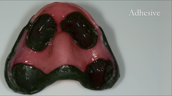
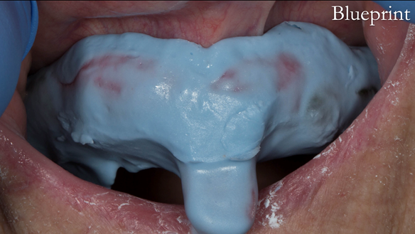
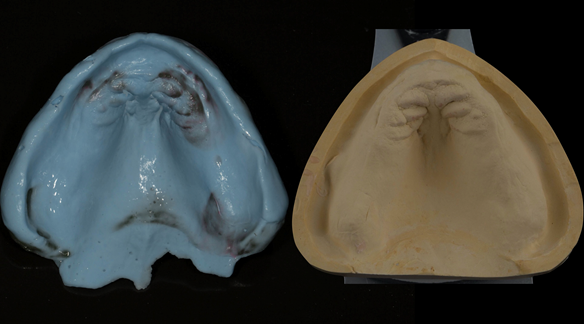
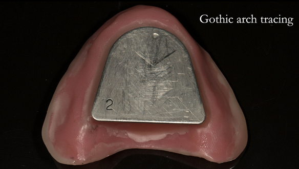
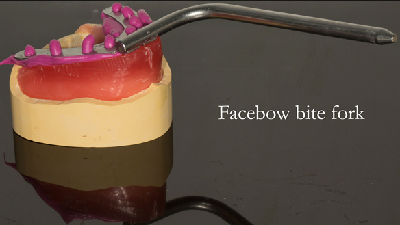
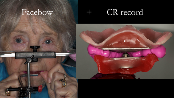
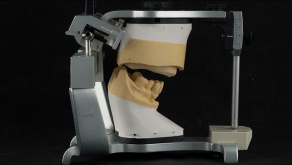
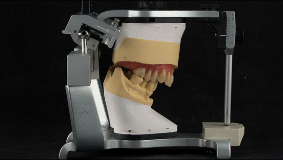
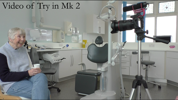
The clinical situation and treatment process is shown in detail below with photographs. In addition, threre is a link to the a 45 minute webinar I gave explaing this case. I provided the clinical work and Rowan Garstang provided the technical work.
If you enjoy my Newsletters and you have friends, colleagues, dental students, dental technicians, clinical dental technicians and postgraduate dentists that you think will appreciate them, please feel free to share them. In addition, if your colleagues would like to receive our Newsletters please email me and I will add them to the email list.
If you would like to learn more about making superb immedaite dentures please clik this link.


Reference material
Full access PDF to my published scientific papers which explain my philosophy and clinical techniques. Please click on the link below and scoll down this page to find lots of useful clinical techniques, reference material and previous lectures:
https://www.finlaysutton.co.uk/speaking